I have been toying with the idea of making a Si5351A breakout board ever since I saw the chip details on Silicon labs web site. It seems SI5351A is an ideal choice for Variable Frequency Oscillator (VFO) for a homebrewed radio. The SI5351 is an i2c programmable any frequency clock generator. The chip can generates up to 8 non-integer-related frequencies from 8 kHz to 160 MHz depending on the model. There are 3 different variations of the chip currently available. For the home brewer SI 5351A looks promising as it is available in a 10 pin MSOP package.
For the ham radio home brewer, such a chip which can be programmed over many ham bands offer numerous possibilities. The most obvious choice would be as a VFO. Currently, the analog devices DDS chips are ruling the market. Compared to them the Silicon Labs chips are cheaper and less cumbersome to handle. I am yet to see the noise performance of these two chips compared.
In fact, there are a couple of commercial Si5351A breakout boards targeted at the home brewer. They cost around 10$. But the chip itself cost only 1.33$ on the Silicon Labs website and you need only a few additional components to complete the board. The total cost need not be more than 3 $. Along with a cheap Arduino clone, Si5351A gives you lot of flexibility. An added advantages is that the SI5351A has three independent programmable clock generators. You can combine the VFO and BFO into a single chip.
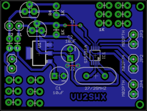
My idea was to build a single side PCB so that any one can build one via toner transfer. Last week, I had a long chat with my friend and colleague Amal Dev about designing a simple board. The board routing was done by Amal Dev on eagle, We have designed an experimental single sided board and it may not be conforming to RF design principles always.
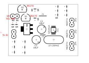
For the interested home brewer a toner transferable image is here. You can buy the SI5351 from RS components or from Mouser. The board is to be powered from a 5v source. The SI5351A needs 3.3v for its operation. The LM1117 is used for generating this. Note that the LM1117 is SMD and is soldered on the copper side. The two MOSFETs ( BS170) are used to convert the I2C levels from 5v to 3.3v. Check the pin outs before you solder. The board can be directly powered from an arduino.
For programming the board you can try the example code from Hansummers. Alternately you can try the excellent si5351 arduino library. Tom Hall AK2B has some sample sketches using this library. Please note that I2C address of the chip may be different from those found in the above code. Please use an I2C scanner to find out your chips address and then modify your code accordingly.


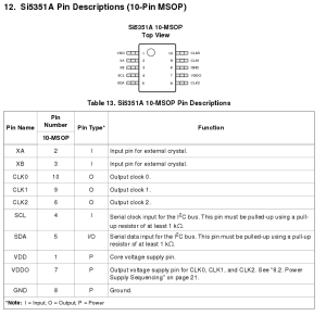
The pin out of the SI5351A is shown below.
A special thanks to Amogh Desai who tested the first version and reported couple of errors. Further comments and error reports are welcome.

Well done sir, this was the most wanted item in the homebrew shack…. congrats and wish to have two piece.
How does this match up or compare with the performance of AD9850? Curious to know!!
I think it is much better than analog ones. I have not done any serious testing.
Very well done, I was following Charudatta Uplap for the same. When the PCB’s will be available? Tentative value of the PCB?