Bitx 20 is a cute QRP transceiver for 20m. The original Bitx 20 was developed by Indian engineer Ashar Frahan. The details of the circuit and other details are available at his website. There is an active yahoo group for bitx builders and there are several mods and add-ons developed by bitx enthusiast all over the world.
I am already having a Bitx20 and I have made contacts with several European and Russian amateurs on 20m. I have been thinking about building a modified version of bitx for 40m for quite some time now. Now that I am on vacation, I have started working on this project last night. I am following the version 3 layout as prepared by VU2WJM OM Rahul for this. The diagram is here.
I will describe my progress along as i build here.
For converting the Bitx 20 to 40m two modifications are to be done. The band pass filter must be redesigned for 40m and the VFO must oscillate around 17MHz. I am planning to get the transceiver working for 20m and then replace the VFO and band pass filter.
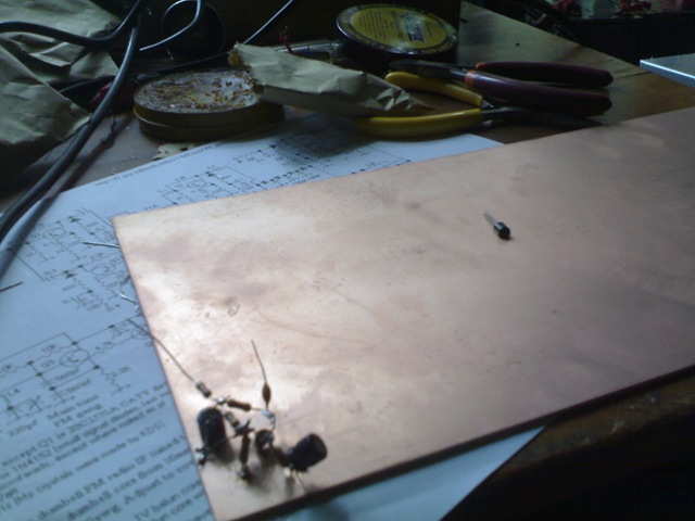
I am following ugly construction method for this project. In ugly construction a plain copper clad sheet is used as a ground plane. All components having connection to ground are soldered on to the copper clad sheet. All other connection are between component leads and not supported on the board.
The following photographs show my progress so far
The microphone amplifier.
This stage was built first and tested by injecting a 50mv 1Khz signal from a signal generator. The stage was giving a gain of nearly 10.

Bitx beat frequency oscillator
I built the above stage next and powered up. The waveform was observed on a CRO and frequency measured with a frequency counter. I was able to vary the oscillator frequency about 20khz by turning the trimmer.
The next step was to wind the trifilar transformer for the mixer. The details are shown below.

Take approximately 105cm of 29 SWG enameled copper wire. Fold them into three as shown above.

Twist the wires together.

Wind 13 turns into a toroid. You can use a TV balun . In that case choose smaller wire diameter( something like 32SWG). Cut the ends of the wires and isolate the three windings. Identify the ends of the windings with a multimeter and mark the windings with marker pen. (You need at least 2 colors). Now the transformer can be installed. Be careful about the polarity of the windings.

The bitx mixer installed on the board.
I will describe further progress later
Why not use a 2.7 – 3 mhz VFO (what I am trying with my bitx?)
I redid the board (up to the mixer) to use almost all SMT components.
I just got my VFO working well.
I am stuck on the bandpass and after and am looking for ideas.
I built a second bitx with 9mhz if and vfo from 1.9 to 2 Mhz . Working perfectly on 40m.
Used 4.7 micro henry moulded inductor in parallel with 100pf and 22pf trimmer for band pass filter. If there are sufficient interest I will post schematic and pictures.
Dear friend,
I made two bitx ,one for 20 mt and one for 40 m,but I need the dada for the coils for the filter and for tha lowpass filter on power amplifier.
Could you help me in this?I can’t find any data on the web.
Thanks a lot.
Ciro IK6AIZ