by R. Jayaraman (VU2JN)
This article is a sequel to the article “A Compact ATU handles 100 watts” that was published online in March 2011. It describes a Norcal-type Antenna Tuning Unit with an in-line Stockton-bridge-type Reflected-power Indicator that I built recently (April 2011). This ATU is also capable of handling the full output of a 100-watt HF transceiver.
The ATU circuit is that of the well-known Norcal BLT ATU, with minor modifications. A Reflectometer, ie. reflected-power indicator, forms part of this ATU and makes it self-contained, obviating the need for a SWR bridge. It is based on the Stockton SWR bridge, an interesting bridge circuit using 2 toroidal RF pick-up coils. This circuit deserves to be used more commonly by hams. For those who are interested, additional details of the Norcal BLT ATU and the Stockton SWR Bridge are available on the internet.

Fig.1. Circuit diagram of the ATU with Reflectometer
The toroidal coil of the Norcal ATU has been replaced with an open air-core coil since this unit is meant as a prototype suitable for duplication by budding hams who might find it difficult to procure large-sized toroids. The two BC-type 330 pF air-variable tuning condensers were salvaged from old discarded radios. They were tested at 230 V AC to make sure that there was no arcing. If air-variable tuning condensers are not available, polyster-variable tuning condensers may be used, but the maximum RF power may have to be restricted to about 50 W.
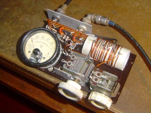
The entire ATU-cum-Reflectometer is assembled on a bakelite sheet 6.25″ by 3.5″ that was available with me. Hams wishing to build this unit are advised to use a slightly broader sheet. The main coil is wound with 16-gauge copper wire on a short length of 1.25″ dia. plastic water-pipe tubing. The coil has 16 turns spaced to a length of 1.5″ with taps at 8 and 14 turns. The centre of the winding is the earth point. In the Norcal ATU, the RF output is taken through a 6-turn link winding, but in this unit, the messy link is dispensed with and the output is taken from a tap 6 turns from the earth point. Even with this simplification, the ATU works satisfactorily.

Fig.2. Photo of the ATU with Reflectometer
The open coil will produce a weak RF field in the shack. If the builder wishes so, the unit can be put in an aluminium box, but then (1) leave a minimum space of one diameter around the coil, (2) since the body of the tuning condensers is not at ground potential, leave a small gap between the shafts of the condensers and the front panel, and (3) use knobs with pointers for the tuning condensers (to indicate their position).
The toroids are 0.38 in. o.d. through which runs a short length of RG-174U coax. The centre conductor of the coax forms the primary of the winding, and the outer braid is used as a Faraday shield by grounding at one end only. The secondary windings of the toroidal pick-up coils consist of 18 turns of 24-gauge copper wire. The 1N34A rectifier circuit is used only on the reflected-power side. If the builder wishes so, this indicator can be easily upgraded to a full-fledged SWR bridge.
The visual indicator is a robust disposal-type 500 uA meter that was available in my junk-box. The resistor that comes in series with the meter should be not less than 5 K, and is selected so that there is a substantial reflected-power indication with a mismatched antenna. Since modern transceivers have built-in SWR protection circuitry, there is some sort of automatic control on the reflected power reading. Therefore no sensitivity control is needed.
With the transceiver and antenna connected to the unit, RF power is applied, and the two condensers are adjusted for zero reflected-power indication. Since no reduction drives are used, the condensers need to be tuned very carefully. A very slight hand-capacitance effect is present, but is not bothersome. The ATU-cum-Reflectometer is performing very well, and is able to tune my coax-fed 40-metre dipole on 80 metres, and bring down the reflected power to zero. To sum up, this is a simple and satisfying homebrew project.
PS: The photo reveals the need for some finishing touches on coil L1 that were initially postponed and then forgotten!
— VU2JN.
Note from VU2SWX : OM Jayaraman has permitted me to play with tis cute tuner . The unit is currently in my shack.