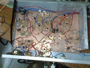
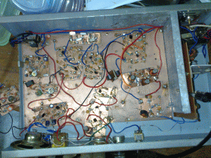
The bitx, I built using the ugly construction method was too ugly to look at. The board was rebuilt using Manhattan style construction last week end . Now the board looks tidy and neat. The added advantage is that I can plug and play with any section. Individual sections are built on smaller PCBs and all sections are glued to a larger copper clad sheet.
However, the power output in transmit mode was very low. Up on investigation , it was noticed that the band pas filter was not performing well.
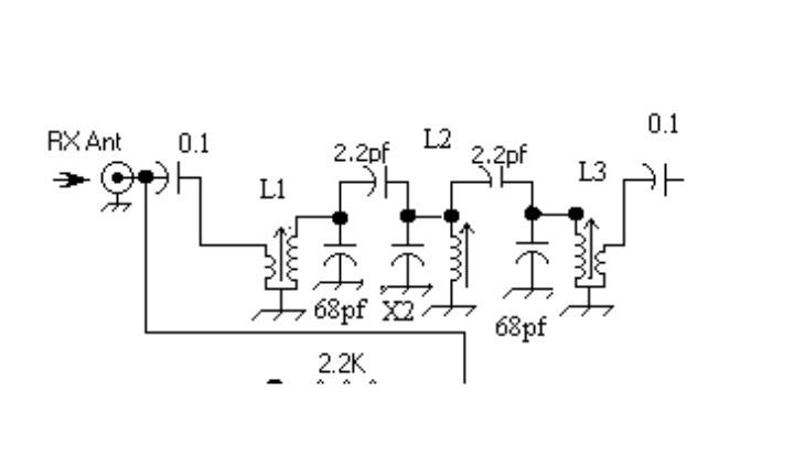
This morning, I decided to experiment with the band pass filter. My board is based on version 3 schematic of the bitx and the band pass filter was built from old IFTs recovered from a junk radio reviver. The filter was not tuning properly. The output at the end of the filter was very low ( 100 mv) May be the ferrite used in the IFT is of inferior quality.
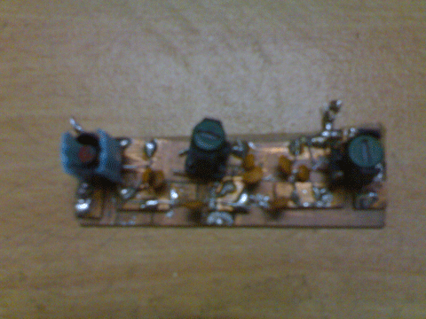
I looked around my junk box and found out some small resistor looking inductors. I decided to try the band pass filter from the original design. This design uses 2 ?h inductors wound on tap washers. Fortunately, I had a few 1?h
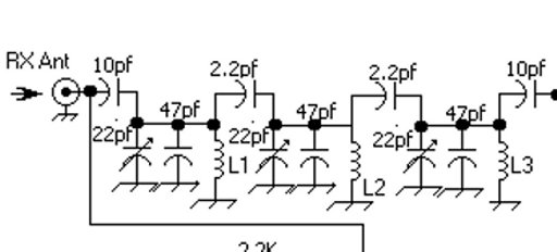
I built the circuit as shown below and soldered it to the board. Oops. The performance went down. I was getting only 50mv on transmit and the receiver performance also suffered. Again ,I suspect the junk box components. I thought of rewinding the coil using tap washer. Ferrite slugs and torrid cores are not easily available in this part of the world.
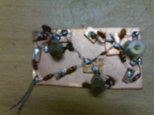
. I looked around the junk box again and found out a set of coils used for 3 band broadcast radio. I decided to rebuild the version 3 band pass filter again
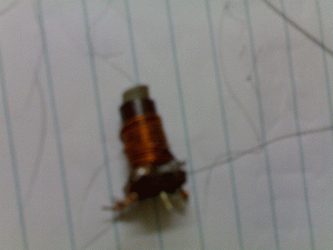
The coils were rewound . I used 11 turns for the main winding and 3 turns for coupling winding The coil inductance was varying form 2.7 to 1.65 micro henries. The completed filter was installed and bitx powered up . Now I was getting around 700mv RF from the filter stage. I am yet to test the power amplifier section . I hope I will get 5 watts as advertised. With the new filter in place the receiver performance has improved tremendously. I can hear lot of stations both on CW and SSB.
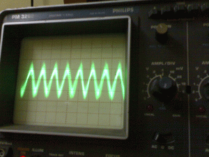
The signal I got while whistling to the mic is also shown below.
I have read your lab notes on experimenting BITX BPF. I appreciate your patience in repeatative work. congratutions for extracting 700mV TX RF. Keep up good work.