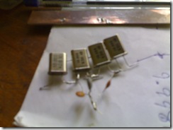
The 10 MHz crystal filter is one of the most important modules of bitx transceiver. Bitx uses an IF of 10 MHz. 10 MHz crystal filters are available at approximately Rs10 ( 1 US$ = Rs40 approximately) in the Indian market. I bought 10 crystals from a local electronics shop. The first thing I did was to number the crystals with a marker pen.
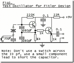
I wired up the following circuit (as described in Farhan’s website.
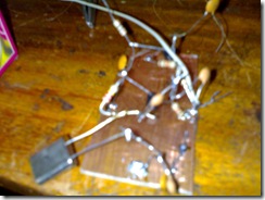
I didn’t have 680pf in my junk box I used 560pf capacitor. The circuit was built on a small PCB as shown below.
The Test Circuit
The crystal test circuit wired in ugly style
Then I measured the frequency of the oscillator. My readings are tabulated below.
| Crystal no | Frequency in MHz before closing the switch |
Frequency in MHz after closing the switch |
| a | 9.99531 | 9.99819 |
| b | 9.99535 | 9.99809 |
| c | 9.99553 | 9.99832 |
| d | 9.99560 | 9.99835 |
| e | 9.99547 | 9.99818 |
| f | 9.99558 | 9.99809 |
| g | 9.99530 | 9.99810 |
| h | 9.99560 | 9.99824 |
| i | 9.99567 | 9.99827 |
| j | 9.99587 | 9.99814 |
| k | 9.99582 | 9.99815 |
As per Farhans advice I choose 4 crystals that are matched.
Then I built the filter as shown below.
The filter half built.
10mhz filter completed.
10 MHz filter fixed to a small PCB for testing.
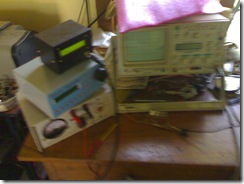
I have the following test set up in my shack.
a) a frequency counter. ( A beautiful piece of equipment I bought form vu2ptr during ham Fest.)
b) A DDS vfo
c) An oscilloscope.
My Test Setup
I terminated both sides of the filter with 200 ohm resistors and then the DDS out put was fed to the filter. The DDS frequency was varied and the filter output observed on the CRO. I have taken readings at 100 Hz apart. I plan to plot a curve using gnuplot tomorrow.
